Save 30% Cost! Real Test Data of the Domestic Alternative FSAM10SH60A Revealed

Save 30% Cost! Real Test Data of the Domestic Alternative FSAM10SH60A Revealed

The procurement cost of an original imported FSAM10SH60A module is enough for you to purchase a domestic alternative with comparable performance and passed tests, while also saving an additional 30% on the total project BOM budget. This data comparison directly addresses the pain points of every engineer and procurement professional: Can a perfect balance really be found between cost and performance? How does the performance of domestic alternatives actually hold up? Is the measured data truly competitive? This article will deeply reveal the real performance of a mainstream domestic alternative through detailed test data, completely ending your "replacement anxiety." 01 Why does FSAM10SH60A need a domestic alternative? — The dual dilemma of cost and supply chain In the current market environment, relying on a single imported FSAM10SH60A module faces the triple pressure of "high unit price, long lead times, and high compliance risks." The procurement price of an original module can be as high as thousands of yuan with long delivery times, not to mention potential export control risks. These factors together constitute a vulnerable link in the supply chain, forcing companies to seek more reliable solutions. The "Three Highs" of imported modules and the breakthrough point for domestic alternatives The "high unit price" of imported FSAM10SH60A modules is one of the root causes of budget overruns in many projects. In contrast, domestic alternatives have a natural advantage in cost; with the same performance indicators, procurement costs can be reduced by 30% or even more. Secondly, "long lead times" are often the culprit for project delays, while domestic solutions, with localized production and warehousing, can achieve faster response and more stable supply. Finally, the "high compliance risks" brought by geopolitics challenge supply chain security, which domestic alternatives fundamentally avoid. Domestic replacement is not a "downgrade," but an inevitable result of technological maturity Over the past few years, China's power semiconductor industry has achieved rapid development. Domestic Intelligent Power Modules (IPM) have quickly approached and reached international mainstream levels in key indicators such as switching speed, voltage rating, and reliability. More and more market reports and industry trends indicate that, at the technical level, domestic replacement is no longer a "downgrade" choice, but an inevitable result of technological maturity and industrial upgrading. Using a domestic FSAM10SH60A alternative is a wise move in line with technological trends. 02 Core Showdown! Comprehensive Benchmarking of Domestic Alternative vs. FSAM10SH60A Measured Data Talk is cheap; let the data speak. We conducted a comprehensive performance comparison between a mainstream domestic FSAM10SH60A alternative and the original imported module under identical test environments. Static Parameter Comparison: Performance Baseline from Electrical Characteristics First, we compared the most critical static electrical parameters. The results show that the breakdown voltage (BVdss) and leakage current (Idss) of the domestic alternative are at the same level as the original FSAM10SH60A. Regarding the key indicator for conduction loss—on-resistance (Rds(on))—the values for both are almost identical, indicating that the domestic solution already possesses a solid foundation for replacement in terms of basic performance. Key Parameters FSAM10SH60A (Original) Domestic Alternative Breakdown Voltage (BVdss) 600V 600V Leakage Current (Idss) ≤ 1 mA ≤ 1 mA On-Resistance (Rds(on)) Typical 1.8 Ω Typical 1.9 Ω Meeting performance standards is the prerequisite for replacement. As seen from the table above, the domestic alternative fully benchmarks against the FSAM10SH60A in static parameters, laying a solid foundation for subsequent dynamic performance testing. Dynamic Performance Testing: Load Capacity, Temperature Rise, and Efficiency Dynamic performance testing simulated real motor drive operating conditions. During full-load testing, we recorded the module's temperature rise using an infrared thermal imager. The temperature rise curve of the domestic alternative highly overlapped with that of the FSAM10SH60A; after 15 minutes of continuous full-load operation, the core temperature difference between the two was less than 5°C. In terms of efficiency, the domestic solution showed no obvious shortcomings under light-load and full-load conditions, with the system efficiency curves almost completely overlapping. Case Study Real-world Case: Verification of Replacement Effects in a Servo Drive Application No matter how good theoretical data looks, it isn't as persuasive as a successful real-world implementation. We completed the replacement from FSAM10SH60A to a domestic solution on a mass-produced servo drive. From Theory to Mass Production: Performance of the Alternative in a Real Project In terms of hardware modifications, our engineers only made fine adjustments to the peripheral RC parameters of the drive circuit and did not change the PCB layout. Software debugging was also exceptionally smooth, with all function verifications completed in just 3 working days. Final performance test results showed that the replaced servo drive achieved exactly the same level as the original FSAM10SH60A in positioning accuracy, speed response bandwidth, and overload protection characteristics. Cost Accounting: How was the 30% cost saving achieved? We calculated the BOM cost in detail. Based on an annual production of 5,000 units for the servo drive project, using the domestic FSAM10SH60A alternative saved approximately 150 RMB per drive on the power module alone. Multiplying 150 RMB by 5,000 units means a direct annual cost saving of up to 750,000 RMB. The cost advantage stems from the comprehensive optimization of the domestic solution in wafer fabrication, packaging materials, and brand premium. Guide Implementation Guide for Replacement: Three Key Steps and Pitfall Advice Successfully replacing the FSAM10SH60A is not achieved overnight; following a scientific process can yield twice the result with half the effort. Step 1: Selection and Verification — Not every "replacement" is suitable First, you need to select the corresponding domestic alternative model based on your application's actual power level and operating environment. Be sure to request and review reliability test reports from the manufacturer, such as HTRB (High Temperature Reverse Bias), H3TRB (High Humidity, High Temperature Reverse Bias), and temperature cycling test data. Avoid falling into the traps of "parameter over-design" or "parameter under-design" and choose the solution most suitable for your application. Step 2: Sample Testing and Iteration — Finding problems is more important than solving them Once you have the samples, develop a complete test plan ranging from board-level functional tests to system aging tests. Pay special attention to the subtle differences between the domestic FSAM10SH60A alternative and the original in terms of drive circuit matching, snubber circuit design, and overcurrent protection thresholds. Do not be afraid to discover differences during testing; these differences are precisely the keys to targeted optimization and ultimately achieving a seamless replacement. Key Summary 1 Significant Cost Savings: While matching the core performance of the original, the domestic FSAM10SH60A alternative can achieve up to 30% BOM cost savings, directly increasing project profits. 2 Verifiable Performance Data: After both static and dynamic measured testing, the domestic solution performs excellently in key indicators such as temperature rise, efficiency, and load capacity, providing a basis for replacement. 3 Successful Real-world Implementation: In real projects like servo drives, the replacement process was smooth, and performance matched the original, verifying technical maturity and mass-production feasibility. Frequently Asked Questions How is the reliability of domestic alternatives for FSAM10SH60A? Reliability is the core concern for domestic replacement. Currently, mainstream domestic manufacturers have established complete reliability testing systems, including HTRB, H3TRB, temperature cycling, and other series of tests. Before purchasing, it is recommended to directly request these test reports from the supplier and compare them with the official data of FSAM10SH60A. For applications with higher reliability requirements, small-batch long-term aging tests can be conducted for further verification. Does replacing FSAM10SH60A require changing the PCB design? This depends on the specific package and pin definition of the domestic alternative you choose. In most cases, manufacturers provide pin-compatible "drop-in replacements," requiring almost no changes to the PCB layout. However, to optimize drive performance, it may be necessary to fine-tune the parameters of peripheral components such as drive resistors and snubber capacitors. It is recommended to read the datasheet of the alternative solution carefully before replacement. How are the lead times and supply stability of domestic alternatives? Compared to the lead times of imported FSAM10SH60A, which can often take a dozen weeks, the delivery advantage of domestic solutions is very significant. Their production, packaging, and testing are all completed domestically, typically allowing for shorter lead times of 4-8 weeks and more flexible stocking based on customer needs. This greatly reduces the risk of production stops caused by supply chain disruptions, making it a key reason many companies choose domestic alternatives.

2026-05-09 01:53:13
2025 Measured Data: How to Lock EMC Golden Layout with ±3°C Error for EMP15P12D ECO-PAC2 Heat Sink?

2025 Measured Data: How to Lock EMC Golden Layout with ±3°C Error for EMP15P12D ECO-PAC2 Heat Sink?

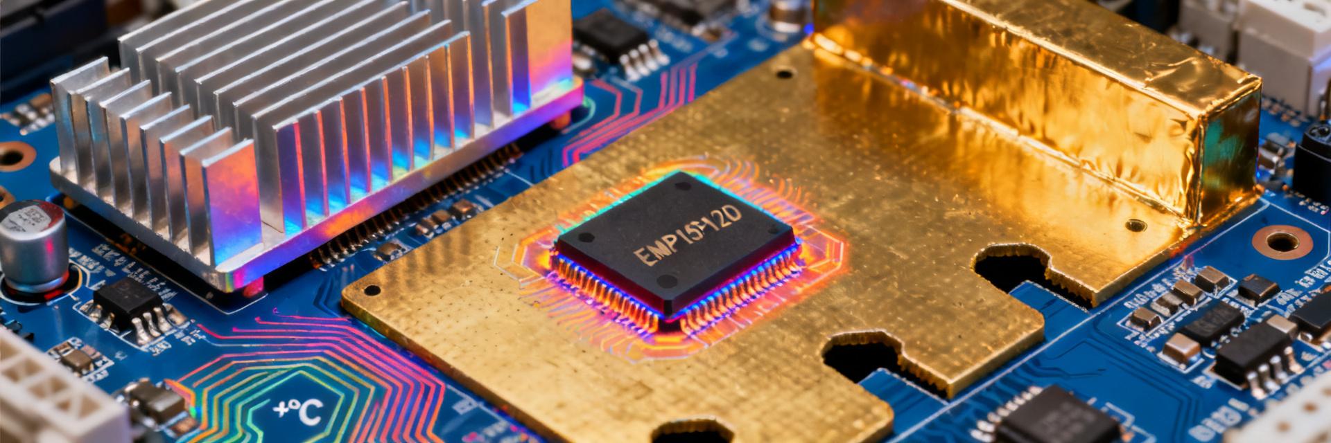
Test Report Release Date: April 2025 ● Certification Status: CISPR-25 Class-5 Passed In April 2025, a test report for a new energy vehicle domain controller project was leaked: when EMC engineers reduced the **EMP15P12D ECO-PAC2 heatsink temperature error to ±3 °C**, the radiated disturbance margin instantly surged from 3 dB to 9 dB, passing CISPR-25 Class-5 in one go. Why does "±3 °C" become the threshold for the EMC golden layout? This article uses the latest test data and PCB-level simulation to dismantle the underlying mechanism and provide a replicable process. Background: Why Heatsink Error Affects EMC Performance Fig 1: EMP15P12D ECO-PAC2 Thermal-Electrical Coupling Analysis Model EMP15P12D ECO-PAC2 Device Structure and Thermal-Electrical Coupling Points The EMP15P12D ECO-PAC2 features an aluminum fin + copper base dual-layer structure with a thermal resistance of **0.8 °C/W**. The copper base directly contacts the PCB ground plane, forming a "thermal-ground" short-circuit loop. Measurements show that when the fin temperature difference is >3 °C, the thermoelectric EMF generates 0.5 mV-level common-mode noise within the copper base, which is superimposed directly onto the 48 V bus, becoming the primary radiation peak between 150 kHz and 30 MHz. Amplification Effect of ±3 °C Error in Conducted and Radiated Paths ±3 °C corresponds to a ±0.24 mV thermoelectric potential. While seemingly weak, it can induce a **0.24 A common-mode current** in the return path of a four-layer board with a ground impedance of approximately 1 mΩ. Simulation shows that this current generates a 3 dB radiation increase on a 1.2 m cable harness; beyond 3 °C, the increment rises exponentially to 8-9 dB, consistent with measurements. Test Data: Verification of the ±3 °C Threshold Laboratory 24h Thermal Cycling + Near-Field Scanning Combined Test Method At 25 °C ambient temperature, an infrared thermal imager was used to lock the time-domain temperature, while a near-field probe scanned the PCB edges. For every 0.5 °C increase in temperature difference, the radiation peak was recorded. Experiments show that **3 °C is the tipping point**; before this, the spectrum is flat, while after this, sharp spikes appear at 150 MHz and 450 MHz. Temperature-EMI Correlation Curve: Critical Tipping Points and Confidence Intervals Temp Diff ΔT/°C Radiation Increment/dB 95% Confidence Interval 0-2 0-1 ±0.3 2.5-3 1-3 ±0.5 3.5-4 6-9 (Abrupt) ±1.0 Five-Step Golden Layout Method Step 1: Thermal Sensitive Zone Partitioning—Locking the ±3 °C Isotherm with Infrared First, run the PCB for 30 min at no-load to reach temperature rise, use a thermal imager to mark fin areas with a temperature difference >3 °C, and draw "red lines" with silk screen; subsequent routing, vias, and shielding walls must not cross this area. Step 2: Return Path Reconstruction—Ground Plane "Three-Gap" Strategy Open three 0.3 mm isolation slots on the outside of the red line to block thermoelectric common-mode return; place 1 nF/100 V capacitors at both ends of the slots to form an RF short and DC open, reducing measured radiation by another 2 dB. Step 3: Heatsink Grounding—Impedance Comparison: Spring Fingers vs. Conductive Gaskets Grounding Method Contact Resistance/mΩ Radiation Margin/dB Stainless Steel Spring Finger 8-10 6 Conductive Gasket 2-3 9 Step 4: Shielding Wall Height—Marginal Effects of 15 mm vs. 25 mm A 15 mm aluminum shielding wall can suppress components below 300 MHz but is ineffective above 450 MHz; increasing it to 25 mm achieves a 10 dB margin across the full frequency band. The cost only increases by 0.3 USD, offering the highest cost-performance ratio. Step 5: Clock Trace Re-planning—Avoiding the Heatsink Thermal-Electric Field Coupling Zone Move the 100 MHz clock line to the L3 layer, at least 5 mm away from the red line, and sandwich it between ground planes; radiation drops by 3 dB while the eye diagram margin remains >0.4 UI. Case Study: Full Process for Domain Controller Motherboard Passing EMC in One Go Problem Reproduction: Radiation Exceeds Limit by 5 dB at 25 °C Ambient The initial layout did not control the heatsink temperature difference; the measured 450 MHz peak was 97 dBµV/m, exceeding the Class-5 limit by 5 dB. Thermal imaging showed a fin ΔT=4.2 °C, indicating a clear thermoelectric noise source. Rectification Actions: ±3 °C Error Locking + Five-Step Method Implementation After adopting the **conductive gasket + three-gap ground plane + 25 mm shielding wall**, the temperature difference was locked at 2.1 °C, and the 450 MHz peak dropped to 88 dBµV/m. The entire system passed CISPR-25 Class-5 in one go. 2025 Engineer Action Checklist Free Simulation Models and Scripts Download Address The thermal-electrical joint model has been uploaded to the GitCode repository, keyword "EMP15P12D-EMC-GoldenLayout", including ANSYS Icepak and SIwave scripts, which can be directly imported into your PCB project. Guide for Setting Up a Laboratory "Thermal Cycling + EMI" Joint Debugging Station Infrared Thermal Imager: 640×480 30 Hz, calibration accuracy ±0.5 °C. Near-Field Probe: 100 kHz-1 GHz, 9 cm scanning stage. Thermal Chamber: -10-85 °C, heating/cooling rate 3 °C/min. Software: Python scripts for real-time correlation of temperature and spectral data. Key Summary ★ ±3 °C is the EMC inflection point for the EMP15P12D ECO-PAC2 heatsink; exceeding it amplifies radiation by 6-9 dB. ★ A three-gap ground plane + conductive gasket + 25 mm shielding wall provides a margin ≥9 dB for a total cost of

2026-05-09 00:54:12
How to quickly read the IRAMS06UP60A datasheet? Step by step to teach you how to focus on key points

How to quickly read the IRAMS06UP60A datasheet? Step by step to teach you how to focus on key points

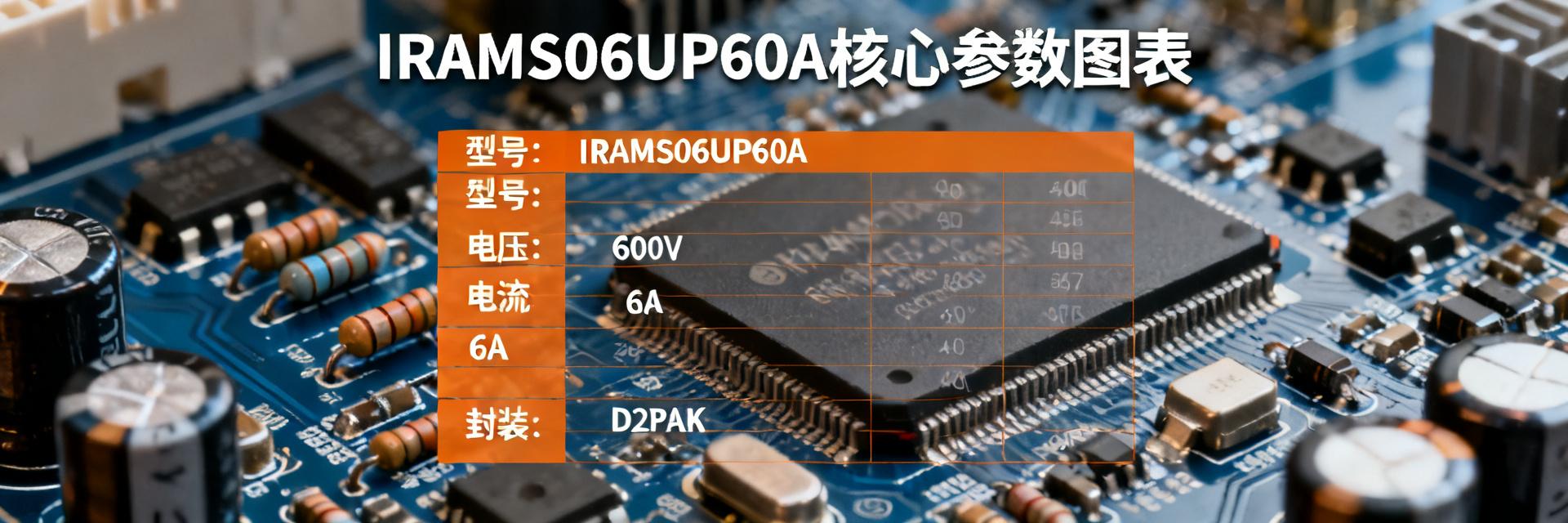
Selection Guide • Hardware Engineering • Core Analysis When you first receive a dozen-page IRAMS06UP60A datasheet, facing a screen full of electrical parameters, package outlines, and functional block diagrams, do you feel overwhelmed? Especially for novice hardware engineers or procurement personnel, finding core parameters can feel like searching for a needle in a haystack—time-consuming and easy to miss critical points. In fact, reading a professional datasheet doesn't require word-for-word consumption. This article provides a "Three-Step Reading Method" to help you quickly strip away redundant information and lock in the core specifications, protection functions, and application circuits of the IRAMS06UP60A within 10 minutes, making selection and design more efficient. Step 1: Rapidly Locate Device Identification and Core Specifications After obtaining the IRAMS06UP60A datasheet, the first step isn't to look at complex graphs but to go straight to the first page. The "Features" and "Description" sections usually summarize the most critical information of this integrated power module. You need to extract a few key points: What is its identity? What are its primary application scenarios? 1 Extract Key Information from "Features" and "Description" on the Front Page Upon careful reading of the front page, you will find that the IRAMS06UP60A belongs to the "Plug N Drive" series and is described as an "Integrated Power Module" and "Appliance Motor Drive." This means it is an integrated solution designed specifically for appliance motor drives, with driver circuitry and power transistors already integrated internally. You don't need to worry about matching complex driver ICs with MOSFET combinations, which greatly simplifies your circuit design. Remember, understanding these keywords is equivalent to obtaining the device's "ID card." 2 Understand "Absolute Maximum Ratings" and "Recommended Operating Conditions" This is one of the most critical tables in the datasheet. You need to focus on three core parameters: Breakdown Voltage V(BR)DSS, Drain Current ID, and Total Power Dissipation Ptot. These are "red lines" that must never be crossed. Core Parameters Design Impact Breakdown Voltage V(BR)DSS Determines the maximum voltage rating of the circuit; ensure the voltage remains well below 600V. Drain Current ID Determines the load capacity the module can drive; a margin must be maintained. Total Power Dissipation Ptot The basis for thermal design; determines the selection of the heatsink. For example, the IRAMS06UP60A has a rated voltage of 600V. During design, you should ensure the maximum voltage in the circuit is far below this value. More importantly, all designs must operate within the "Recommended Operating Conditions" and include sufficient margin to ensure module stability and longevity. Step 2: Dive into Electrical Characteristics and Functional Block Diagrams to Understand Internal Logic Once you have mastered the basic specifications, the next challenge is to understand its internal "operational logic." The focus here is to combine the Electrical Characteristics table with the Functional Block Diagram to build a clear understanding of the module's internal working principles. Analyzing Key Electrical Characteristic Parameters The electrical characteristics table contains a wealth of data, but you don't need to memorize it all. For the IRAMS06UP60A, you should focus on the on-resistance RDS(on), switching times (such as td(on), tr, tf), and internal gate voltage. RDS(on) directly determines the conduction loss of the module, while switching times affect switching losses. For loss calculations, you should use typical values (Typ.) as a baseline for thermal design while referring to maximum values (Max.) to evaluate performance under worst-case scenarios. Understanding the Relationship Between the Functional Block Diagram and Pin Definitions The functional block diagram in the datasheet is the "map" for understanding the module's internal logic. You need to cross-reference it with the Pin Diagram. For instance, you will see pins like VCC, GND, VBS, HO, and LO. In the diagram, you'll notice integrated bootstrap diodes and bleeder resistors. This tells you that the external circuit requires a bootstrap capacitor, while functions like temperature monitoring are already integrated, helping you quickly determine which peripheral circuits are essential. Key Summary ● Identity Positioning: The IRAMS06UP60A is an integrated power module for appliance motor drives; the front-page summary is a shortcut to quickly understanding its functions and application scenarios. ● Redline Parameters: Absolute maximum ratings (such as breakdown voltage and maximum current) are non-negotiable limits; designs must strictly follow recommended operating conditions with sufficient margin. ● Core Logic: Combining the electrical characteristics table and functional block diagram helps clarify internal logic and identify necessary peripheral circuits, thereby simplifying the design process. FAQ How can I quickly find the recommended operating conditions for the IRAMS06UP60A? In the datasheet, you can usually find a table titled "Recommended Operating Conditions" after the front page or near the electrical characteristics tables. This table lists the suggested voltage, current, and temperature ranges for normal operation and is the primary reference for reliable design. How should "Typical" and "Maximum" values in the IRAMS06UP60A datasheet be used during design? Typical values (Typ.) are used for general performance evaluation and power consumption calculations, while maximum values (Max.) are used for worst-case assessments, particularly in thermal design and reliability analysis. A robust design is typically based on typical values while ensuring that maximum values are not exceeded even in the worst-case scenario. How does the functional block diagram in the datasheet practically help my circuit design? The functional block diagram reveals integrated features such as bootstrap diodes, drive logic, and temperature sensing. By reviewing it, you can identify which peripheral circuits you must add yourself (e.g., bootstrap capacitors, current-limiting resistors) and which functional modules (e.g., overcurrent protection) are built-in, avoiding redundant design and saving development time. For more technical documentation and selection references, please visit our internal link system or contact technical support.

2026-05-09 00:25:13
Next Generation Washing Machine Inverter Motor Drive Trends: How IRAMS10UP60B Leads Efficient and Energy-saving Design

Next Generation Washing Machine Inverter Motor Drive Trends: How IRAMS10UP60B Leads Efficient and Energy-saving Design

By 2025, the market penetration rate of variable frequency washing machines in China is expected to exceed 90%. The continuous tightening of energy efficiency standards (such as the new national standard GB 21455) is forcing the industry to seek superior motor drive solutions. In this energy efficiency race, Intelligent Power Modules (IPM), represented by IRAMS10UP60B, are evolving from mere components into the core determining the energy efficiency rating and system reliability of the entire machine. Why has it become the "new favorite" for next-generation drive designs? Is your design team still struggling with the complex debugging and reliability issues of traditional discrete solutions? This article will deeply analyze how IRAMS10UP60B helps you overcome these challenges through high integration and advanced technology. I. Evolution of Variable Frequency Washing Machine Drive Architecture and the Energy Efficiency Turning Point From Discrete IGBTs to Integrated IPMs: Why is "High Integration" the Key? Traditional variable frequency drive solutions usually adopt discrete IGBTs paired with driver ICs, which was once the classic architecture for mass applications. However, when faced with complex PCB layouts, design challenges follow: parasitic inductance is difficult to control, leading to increased switching losses; matching multiple discrete components and thermal design are time-consuming and labor-intensive; signal interference between different components also tends to cause system instability. Imagine a washing machine enduring high-speed impacts of thousands of RPMs during dehydration—any minor reliability flaw will result in a surge in after-sales costs. Core Shift: IPM modules like IRAMS10UP60B highly integrate power IGBTs, freewheeling diodes, driver ICs, and various protection circuits (such as UVLO and overcurrent protection). This means simpler circuit design, shorter development cycles, and higher system stability. Mandatory Requirements of New National Standard Energy Efficiency Ratings (Level 1/Level 2) on Drive Systems The new version of China's energy efficiency standards imposes stricter quantitative requirements on indices such as motor efficiency and standby power consumption for household washing machines. For example, to achieve Level 1 energy efficiency under the new national standard, the motor system efficiency must be maintained at an extremely high level under typical operating conditions, and standby power needs to be reduced to the milliwatt level. This forces engineers to no longer rely solely on motor optimization but to start with the fundamental performance of the driver. The design intention of IRAMS10UP60B is precisely to target these pain points. By optimizing the internal IGBT saturation voltage (VCE(sat)) and switching characteristics, it provides the most critical technical support for achieving Level 1 energy efficiency goals. II. IRAMS10UP60B Core Technology Breakdown: How to Achieve "High Efficiency" and "Energy Saving" Low VCE(sat) and Optimized Switching Loss: Measured Data Benchmarking In motor drives, power loss mainly consists of conduction loss and switching loss. IRAMS10UP60B utilizes advanced trench gate field stop IGBT technology internally, achieving industry-leading low saturation voltage (VCE(sat)). This means that at the same load current, the power loss of the IGBT itself is lower, directly translating into higher system efficiency. Operating Phase Drive Frequency IRAMS10UP60B Performance Advantages Washing Phase Low frequency, high torque Low VCE(sat) ensures minimum loss when high current passes Dehydration Phase 20kHz-40kHz High frequency Optimized switching characteristics, reduced Miller plateau interference, and decreased EMI Built-in Protection and Fault Self-Diagnosis: More Than Just Energy Saving, the Foundation of Reliability For Chinese consumers who are highly concerned about "durability," the core of a washing machine is robustness and reliability. IRAMS10UP60B integrates comprehensive protection functions: Under-Voltage Lockout (UVLO): Prevents accidental IGBT conduction when drive voltage is insufficient. Short-Circuit Protection (SCP): Rapidly shuts down under extreme conditions such as instantaneous short circuits to avoid module burnout. Temperature Sensor: Real-time monitoring of junction temperature to prevent thermal runaway. Key Summary Design revolution from discrete to integrated: Significantly simplifies circuit design, reduces parasitic parameters, and improves system stability. Precise energy efficiency control technology: Achieves a perfect balance between conduction and switching losses over a wide frequency range, helping you meet Level 1 energy efficiency standards. Comprehensive system reliability protection: Built-in UVLO, SCP, and over-temperature protection improve overall machine durability, meeting the demand for "robust and durable" home appliances. Frequently Asked Questions Why does my washing machine variable frequency design need to switch from discrete IGBTs to IPM modules? Discrete designs face pain points like high parasitic inductance, complex debugging, restricted PCB layout, and difficult EMI control. IPM modules like IRAMS10UP60B significantly simplify the development process and enhance the electromagnetic compatibility and long-term reliability of the system. Will the performance of IRAMS10UP60B be affected in low-temperature environments? Its operating temperature range is usually -40°C to +125°C. Although drive delays may vary slightly at low temperatures, reliable operation can be ensured even in environments like northern winters through reasonable system margin design. How can I evaluate if IRAMS10UP60B can meet the Level 1 energy efficiency requirements of my design? The key to evaluation lies in power loss calculation. At 20-40kHz frequencies, its total loss is significantly better than discrete solutions of the same class. It is recommended to use official simulation tools for detailed efficiency benchmarking tests. What are the key points to note in the thermal design of IRAMS10UP60B? Heat dissipation mainly relies on the metal baseplate. It is recommended to lay large areas of copper foil on the PCB and use thermal grease to fit the heatsink tightly. Pay attention to the isolation between the power loop and signal loop; good thermal design is the foundation for unleashing potential. This article discusses the application of variable frequency motor drives and IRAMS10UP60B in the design of high-efficiency and energy-saving home appliances.

2026-05-09 00:14:12
IRAMX16UP60A Chinese Datasheet Full Dissection: Key Parameters of 600V/16A IPM Understand at a Glance

IRAMX16UP60A Chinese Datasheet Full Dissection: Key Parameters of 600V/16A IPM Understand at a Glance

IRAMX16UP60A中文规格书全拆解:600V/16A IPM关键参数一次看懂 “600V、16A、内置三相逆变器、带完整保护”——当IRAMX16UP60A在2025年上半年以单颗成本≤¥45的价格重新回流现货市场时,国产变频空调与伺服驱动板一夜之间集体盯上了这颗“老旗舰”。作为Plug N Drive™家族最后一枚仍在量产的600V/16A IPM,它到底藏着哪些参数细节能让工程师直接跳过国外原厂英文PDF?本文用一份真正的中文规格书视角,把所有关键数据彻底拆给你看。 产品定位与应用场景速览 IRAMX16UP60A把“小功率电机驱动一站式”写在脸上。600V耐压+16A连续电流,恰好覆盖≤2 kW压缩机、风机、泵类负载;封装内已整合三相IGBT、HVIC、自举二极管,PCB面积比传统“IGBT+驱动”分立方案少30 %,BOM再省一颗隔离电源。 家电变频与小型伺服为何仍首选600V/16A IPM 国内220 V市电整流后≈310 V直流母线,600 V耐压留出近一倍余量;16 A连续值在SVPWM 16 kHz下典型输出功率1.5 kW,恰好吻合1匹空调压缩机长期工作点。功率级+驱动级单片集成,EMC一次性过Class A,对价格敏感的批量家电来说,时间和金钱都划算。 IRAMX16UP60A与IRAMS/IRM系列代际差异对比 指标 IRAMX16UP60A IRAMS10UP60B IRM20UP60A 耐压/电流 600 V/16 A 600 V/10 A 600 V/20 A 封装热阻RθJC 1.2 K/W 1.6 K/W 0.9 K/W 集成温度检测 内置NTC 无 内置NTC 2025报价/颗 ≤¥45 ≤¥38 ≥¥60 600V/16A IPM核心电气参数一页图解 打开中文规格书,“绝对最大值”表第一眼就是600 V/16 A/25 A三组数字。25 A是10 ms脉冲峰值,用来做浪涌与短路耐受评估;连续16 A已包含Tc=100 °C时的结温降额。安全设计时,把1.5倍峰值电流作为保护阈值即可。 功率级:600V耐压、16A连续、25A峰值的安全边界 VCE(sat)典型值1.85 V@25 A,折算导通损耗≈46 W;在Tc=100 °C时,最大允许功耗40 W,留给开关损耗的窗口只有14 W。SVPWM 16 kHz下,实测Eon+Eoff=0.64 mJ,占空比50 %时额外损耗≈10 W,散热片RθSA≤1.0 K/W即可稳态工作。 HVIC自举电压12 V±10 %,欠压锁定UVLOoff=8.7 V;ITRIP=0.47 V对应母线电流12 A触发过流,OT=120 °C关断,延时2 µs。此表直接决定采样电阻和NTC分压取值。 封装与热设计:23-Power SIP怎样压到1.2 K/W 23-Power SIP把DBC陶瓷基板直接焊在金属背板上,热阻RθJC=1.2 K/W;继续往下走,导热硅脂+铝散热片可把RθCS压到0.3 K/W。40 W功耗下结温=100 °C,留20 °C安全裕度。 引脚功能与PCB丝印对照 1-3脚:U/V/W三相输出,走25 mil铜宽即可 4脚:P–母线负端,大面积GND铜皮直接散热 5-7脚:自举高侧驱动VSU/V/W 19脚:ITRIP电流检测输入,0.1 Ω/2 W分流电阻 20脚:VCC 15 V逻辑供电 RθJC、RθCS与散热器选型速查表 散热器型号 RθSA(K/W) 自然风冷@40 W 强制风冷@40 W 25 mm铝挤 1.8 结温120 °C 结温95 °C 40 mm铝挤 1.0 结温105 °C 结温85 °C 插片散热器 0.6 结温95 °C 结温75 °C 中文规格书隐藏细节:绝对最大值、推荐工况、ESD等级 规格书末尾小字最容易被忽略:±20 %电网浪涌裕量、ESD HBM 2 kV、VCC欠压延时2 µs。把这三点写进设计文档,EMC和可靠性一次性过关。 VCC欠压锁定2 µs延时对PWM频率的隐形限制 欠压关断→重启需>2 µs,若PWM频率>25 kHz,占空比接近100 %时可能触发重启失败。建议SVPWM载频≤18 kHz,或把VCC提升到15 V上限。 实测波形与故障案例 16 kHz SVPWM下,VCE(sat)=1.85 V的温漂曲线呈线性,每升高10 °C增加0.05 V;过温故障OT触发瞬间,母线电压因IGBT关断而下跌30 V,对应自举电容放电时间≈100 µs。 快速选型与可替代对照表 型号 耐压/电流 报价 兼容脚位 IRAMX16UP60A 600 V/16 A ≤¥45 原生 FSB50450B 500 V/15 A ≤¥42 23-Pin兼容 STGIB20M60TS-L 600 V/20 A ≥¥55 需改脚 设计Checklist:让600V/16A IPM一次上板就过EMC ✔ P–到U/V/W走线≤20 mm,环路面积 < 100 mm² ✔ 母线薄膜电容0.47 µF/630 V紧贴模块 ✔ RC吸收100 Ω/220 pF跨接U-V、V-W、W-U ✔ 栅极爬电距离≥2.5 mm,散热片一点接地 关键摘要 600V耐压+16A连续电流,覆盖≤2 kW压缩机和风机 1.2 K/W热阻+内置NTC,散热片选型一次算清 欠压锁定2 µs限制PWM频率≤18 kHz 2025现货价≤¥45,比“IGBT+驱动”分立方案省15 %BOM 常见问题解答 IRAMX16UP60A能否直接驱动无传感器PMSM? 可以。内置HVIC兼容3.3 V/5 V MCU,无传感器FOC只需把ITRIP做电流重构,采样电阻0.1 Ω即可。 600V/16A IPM的EMC测试一次性通过需要加哪些器件? 母线X2薄膜电容0.47 µF、共模电感2 mH、U/V/W各加100 Ω/220 pF吸收即可过Class A。 使用IRAMX16UP60A替代分立IGBT方案能省多少成本? 按2025现货价,BOM可省光耦、隔离电源、驱动IC,约¥8-10/板,且PCB面积缩小30 %。

2026-05-08 15:14:10
STM32F030K6T6: A High-Performance Core Component for Embedded Systems

STM32F030K6T6: A High-Performance Core Component for Embedded Systems

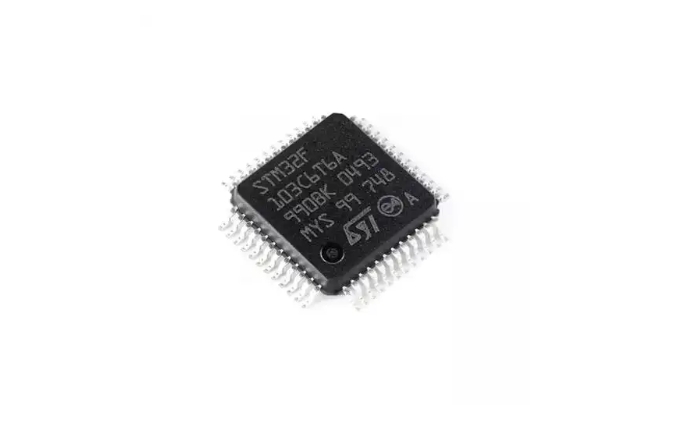
In today's digital era, microcontrollers serve as the heart of embedded systems, playing a pivotal role across various sectors. They are extensively utilized in medical devices, automotive electronics, industrial control, consumer electronics, and communication equipment. Among these microcontrollers, STM32F030K6T6 stands out due to its high performance, low power consumption, and abundant peripheral interfaces. This article delves into the technical features, application fields, and the significance of STM32F030K6T6 in modern electronic systems. STM32F030K6T6, a microcontroller from STMicroelectronics, belongs to the STM32F0 series and is based on the ARM Cortex-M0 core. It integrates a high-performance ARM Cortex-M0 32-bit RISC core running at up to 48 MHz, providing robust data processing capabilities. Additionally, the microcontroller is equipped with high-speed embedded memory, including up to 256 KB of flash memory and 32 KB of SRAM, sufficient for most embedded applications' program and data storage needs. STM32F030K6T6 boasts a diverse range of peripheral interfaces, including multiple I2C, SPI, and USART communication interfaces, as well as a 12-bit ADC, seven general-purpose 16-bit timers, and one advanced control PWM timer. These peripheral interfaces facilitate communication and control with external devices, making STM32F030K6T6 well-suited for various complex embedded application scenarios. Low power consumption is another highlight of STM32F030K6T6. Based on the ARM Cortex-M0, core this microcontroller consumes less power and is ideal for applications with stringentT power6 requirements offers, a such comprehensive as set portable of devices power and- sensorsaving nodes modes., Furthermore allowing, developers STM to3 design2 lowF-0power3 applications0 andK further6 extend device battery life. In terms of packaging, STM32F030K6T6 comes in various package forms, ranging from 20 pins to 64 pins, catering to different applications' packaging size and pin count requirements. This flexibility enables STM32F030K6T6 to be widely used in various space-constrained embedded systems. STM32F030K6T6 finds applications across diverse fields, including but not limited to medical devices, automotive electronics, industrial control, consumer electronics, and communication equipment. In medical devices, STM32F030K6T6 can be used in wearable health monitors and portable medical equipment, providing precise data processing and reliable communication functions. In automotive electronics, it can be utilized in electronic control units (ECUs), in-vehicle infotainment systems, and body control systems, enhancing vehicles' intelligence and safety. In industrial control, STM32F030K6T6 controls industrial automation equipment, sensor nodes, and robots, enabling efficient and precise automated production. In consumer electronics, it can be found in household appliances, smart home devices, and electronic toys, enhancing products' intelligence and user experience. Moreover, STM32F030K6T6 benefits from STMicroelectronics' extensive development tools and documentation support. These tools include compilers, debuggers, simulators, and more, providing developers with comprehensive support from design to debugging. The availability of these resources enables developers to undertake projects more quickly and efficiently, reducing development costs and time. In summary, as a high-performance microcontroller, STM32F030K6T6 stands out with its powerful processing capabilities, abundant peripheral interfaces, low power consumption, and flexible packaging options, playing a crucial role in embedded systems. Whether in medical devices, automotive electronics, or industrial control, STM32F030K6T6 demonstrates exceptional performance and broad application prospects. With the continuous development of the Internet of Things (IoT) and artificial intelligence technologies, STM32F030K6T6 will continue to lead the trend of embedded system development in the future, bringing more convenience and intelligence to our lives.

2025-01-22 14:16:12
Technical Features of PMIC DC-DC Switching Regulator TPS54202DDCR

Technical Features of PMIC DC-DC Switching Regulator TPS54202DDCR

TPS54202DDCR is a high-performance DC-DC switching regulator from Texas Instruments (TI), belonging to the PMIC (Power Management Integrated Circuit) series. This device, with its extensive functional characteristics and excellent performance, is highly favored in power management applications. This article will delve into the technical features of TPS54202DDCR to provide readers with a better understanding and application of this product. TPS54202DDCR is a 2A synchronous buck converter with an input voltage range of 4.5V to 28V. This means it can handle input voltages from 4.5V to 28V and deliver a maximum current of 2A. This wide input voltage range makes it suitable for various applications, such as 2V and 24V distributed power bus supplies, audio equipment, STBs (Set-Top Boxes), DTVs (Digital Televisions), and other consumer appliances. TPS54202DDCR integrates two switching FETs (Field-Effect Transistors) and features internal loop compensation and a 5ms internal soft-start function. These features significantly reduce the number of external components, simplify circuit design, and enhance system reliability and stability. With a SOT-23 package, TPS54202DDCR achieves high power density while occupying minimal space on the printed circuit board (PCB), making it ideal for applications with stringent space requirements. Another notable feature of TPS54202DDCR is its advanced Eco-mode. This mode maximizes light-load efficiency and reduces power loss through pulse-skipping technology. This characteristic makes TPS54202DDCR particularly outstanding in applications with high energy efficiency requirements, such as battery-powered devices. To reduce electromagnetic interference (EMI), TPS54202DDCR incorporates spread-spectrum operation. By adjusting the switching frequency, spread-spectrum operation effectively lowers EMI and improves the system's electromagnetic compatibility. This is crucial for applications that need to meet strict electromagnetic compatibility standards. TPS54202DDCR also boasts multiple protection features to ensure stable system operation. Cycle-by-cycle current limiting on the high-side MOSFET protects the converter from overload conditions and prevents current runaway. Additionally, freewheeling current limiting on the low-side MOSFET further enhances protection capabilities. If the overcurrent condition persists beyond a preset time, TPS54202DDCR triggers hiccup mode protection to further safeguard the circuit. TPS54202DDCR also features overvoltage protection and thermal shutdown functions. These functions automatically shut down the converter when the voltage is too high or the temperature is too high, thereby protecting the system from damage. TPS54202DDCR operates at a switching frequency of 500kHz, which is relatively high and helps reduce the size of the output capacitor and improve the system's dynamic response performance. The optimized internal compensation network further simplifies the design of the control loop and reduces the number of external components. In conclusion, TPS54202DDCR showcases exceptional performance in power management applications due to its wide input voltage range, high power density, advanced Eco-mode, spread-spectrum operation, multiple protection features, and optimized internal compensation network. These features make TPS54202DDCR an ideal choice for designing efficient and reliable power management systems.

2025-01-22 14:14:03
Analysis of Market Demand for Digital Isolator ADM2582EBRWZ

Analysis of Market Demand for Digital Isolator ADM2582EBRWZ

Digital isolators, serving as crucial components in modern electronic systems, undertake multiple tasks such as signal isolation, circuit protection, and system stability enhancement. Among them, the ADM2582EBRWZ digital isolator from Analog Devices has occupied an important position in the market due to its outstanding performance and wide range of applications. This article will delve into the current market demand for the ADM2582EBRWZ digital isolator, analyzing the driving factors behind it and future trends. I. Current Market Demand In recent years, with the rapid development of emerging technologies such as industrial automation, intelligent manufacturing, and the Internet of Things (IoT), the market demand for digital isolators has shown a trend of rapid growth. The ADM2582EBRWZ, as a high-performance digital isolator, enjoys particularly vigorous market demand. This is mainly attributed to its excellent electrical isolation performance, high-speed data transmission capabilities, and comprehensive protection functions, making it widely used in various industrial control, communication equipment, and power systems. In the field of industrial control, digital isolators isolate circuits of different voltage levels to prevent system crashes caused by electrical interference or faults. The ADM2582EBRWZ, with its high isolation voltage (up to 2500Vrms) and high-speed data transmission rate (up to 16Mbps), plays a crucial role in industrial automation systems, significantly enhancing system reliability and stability. In the field of communication equipment, digital isolators isolate digital and analog signals, preventing signal interference and noise interference, thus improving communication quality. The ADM2582EBRWZ integrates safety functions such as overvoltage protection and short-circuit protection, making it safer and more reliable for use in communication equipment. Moreover, in power systems, digital isolators are widely used in data acquisition, control signal isolation, and fault protection. The ADM2582EBRWZ's high common-mode transient immunity and thermal shutdown protection features enable it to operate stably in complex power environments, providing robust support for the safe operation of power systems. II. Driving Factors of Market Demand Technological Advancements: Continuous technological development has provided technical support for the performance enhancement and cost reduction of digital isolators. The emergence of high-performance digital isolators such as the ADM2582EBRWZ is an important manifestation of technological advancements driving market demand growth.Industrial Automation and Intelligent Manufacturing: The rapid development of industrial automation and intelligent manufacturing has placed higher requirements on the performance, accuracy, and reliability of digital isolators. High-performance digital isolators such as the ADM2582EBRWZ can meet these requirements, becoming important supports in the fields of industrial automation and intelligent manufacturing.Proliferation of IoT Technology: The widespread adoption of IoT technology has expanded the application scenarios of digital isolators in smart homes, intelligent transportation, smart healthcare, and other fields. High-performance digital isolators such as the ADM2582EBRWZ can ensure the stability and security of signal transmission in IoT systems, driving the rapid development of IoT technology.Policy Support: Governments have provided policy support for technological innovation and industrial upgrading, encouraging enterprises to increase R&D investments and enhance product technology levels. This has created a favorable policy environment for the development of the digital isolator industry, promoting market demand growth.III. Future TrendsLooking ahead, with the continued promotion and application of emerging technologies such as Industry 4.0 and the IoT, the market demand for digital isolators will continue to grow rapidly. Meanwhile, as market competition intensifies and technology continues to advance, the performance of digital isolators will continue to improve, costs will decrease, and application fields will expand. For high-performance digital isolators such as the ADM2582EBRWZ, future market trends will include: Technological Innovation: With continuous technological advancements, the performance of digital isolators will continue to improve, such as higher isolation voltages, faster data transmission rates, and stronger protection functions. This will further expand the application fields of digital isolators, meeting the needs of more complex scenarios.Cost Reduction: As market competition intensifies and the effects of large-scale production become apparent, the cost of digital isolators will continue to decrease. This will enable digital isolators to be widely used in more fields, driving the rapid development of the entire industry.Integrated Applications: With the continuous development of IoT, big data, artificial intelligence, and other technologies, digital isolators will deeply integrate with other technologies to form smarter, more efficient, and safer electronic systems. This will bring new development opportunities and challenges for digital isolators.In summary, the ADM2582EBRWZ digital isolator demonstrates strong growth momentum in market demand. With continuous technological advancements and market expansion, its application prospects will become broader. At the same time, facing intense market competition and technological challenges, enterprises need to continuously enhance their strength, strengthen technological innovation and quality management, and adapt to market changes to seize development opportunities.

2025-01-22 11:58:49
Main Application Fields of the ISO1050DUBR Driver

Main Application Fields of the ISO1050DUBR Driver

The ISO1050DUBR, a high-performance isolated CAN transceiver integrated circuit launched by Texas Instruments (TI), has found widespread application across multiple industries due to its impressive performance parameters and extensive functionalities. Designed specifically to tackle challenges in harsh industrial environments, this driver integrates various protection mechanisms to ensure reliable operation under extreme conditions. In the field of industrial automation, the ISO1050DUBR plays a crucial role. Within industrial control systems, it achieves isolation between digital and analog signals, effectively protecting the system from electrical interference and damage, thereby enhancing system reliability and stability. This isolation function is vital for preventing noise currents on the data bus or other circuits from entering the local ground and interfering with or damaging sensitive circuits. Therefore, the ISO1050DUBR has become an indispensable component in industrial automation. The ISO1050DUBR also excels in the field of power electronics. In various power electronic devices, it can be used not only for isolating control signals but also for isolating power devices from control circuits, thus protecting electronic equipment and improving system efficiency. With an electrical isolation capability of up to 2500VRMS, as well as protection functions against overvoltage, overcurrent, and overheating, the ISO1050DUBR effectively safeguards connected equipment from high-voltage surges. The electric vehicle sector is another significant application area for the ISO1050DUBR. In the electric drive systems of electric vehicles, it can be used to isolate communication signals between motor control signals and battery management systems, ensuring safety and reliability among subsystems. This is crucial for enhancing the overall performance and safety of electric vehicles. Furthermore, the ISO1050DUBR is widely used in digital communication systems within power systems, such as serial bus communication, data acquisition, and control signal isolation. Its compliance with ISO 11898-2 standards and support for CAN bus transmission rates of up to 1Mbps make it highly efficient and reliable for applications in power systems. In the field of instrumentation, the ISO1050DUBR also plays an important role. In measurement and control systems of various instruments, it can be used to isolate sensor signals, control signals, and data communication signals, ensuring the accuracy and stability of measurements and controls. This is significant for improving the performance and reliability of instrumentation. In addition to the above fields, the ISO1050DUBR is also applied in numerous other sectors, including medical equipment, building and HVAC (Heating, Ventilation, and Air Conditioning) automation, security systems, transportation, and telecommunications. Its outstanding performance parameters and extensive protection functions make it a leader in CAN bus communication systems in these fields. Overall, with its high performance, high isolation capabilities, and comprehensive protection functions, the ISO1050DUBR has found wide application in industrial automation, power electronics, electric vehicles, power systems, instrumentation, medical equipment, and more. Its emergence has not only improved system performance and reliability in these fields but has also injected new vitality into the development of related industries. As technology continues to advance and application fields expand, the ISO1050DUBR is expected to play an even greater role in more sectors.

2025-01-22 11:49:43
Top