
When you first receive a dozen-page IRAMS06UP60A datasheet, facing a screen full of electrical parameters, package outlines, and functional block diagrams, do you feel overwhelmed? Especially for novice hardware engineers or procurement personnel, finding core parameters can feel like searching for a needle in a haystack—time-consuming and easy to miss critical points.
In fact, reading a professional datasheet doesn't require word-for-word consumption. This article provides a "Three-Step Reading Method" to help you quickly strip away redundant information and lock in the core specifications, protection functions, and application circuits of the IRAMS06UP60A within 10 minutes, making selection and design more efficient.
Step 1: Rapidly Locate Device Identification and Core Specifications
After obtaining the IRAMS06UP60A datasheet, the first step isn't to look at complex graphs but to go straight to the first page. The "Features" and "Description" sections usually summarize the most critical information of this integrated power module. You need to extract a few key points: What is its identity? What are its primary application scenarios?
1 Extract Key Information from "Features" and "Description" on the Front Page
Upon careful reading of the front page, you will find that the IRAMS06UP60A belongs to the "Plug N Drive" series and is described as an "Integrated Power Module" and "Appliance Motor Drive." This means it is an integrated solution designed specifically for appliance motor drives, with driver circuitry and power transistors already integrated internally. You don't need to worry about matching complex driver ICs with MOSFET combinations, which greatly simplifies your circuit design. Remember, understanding these keywords is equivalent to obtaining the device's "ID card."
2 Understand "Absolute Maximum Ratings" and "Recommended Operating Conditions"
This is one of the most critical tables in the datasheet. You need to focus on three core parameters: Breakdown Voltage V(BR)DSS, Drain Current ID, and Total Power Dissipation Ptot. These are "red lines" that must never be crossed.
| Core Parameters | Design Impact |
|---|---|
| Breakdown Voltage V(BR)DSS | Determines the maximum voltage rating of the circuit; ensure the voltage remains well below 600V. |
| Drain Current ID | Determines the load capacity the module can drive; a margin must be maintained. |
| Total Power Dissipation Ptot | The basis for thermal design; determines the selection of the heatsink. |
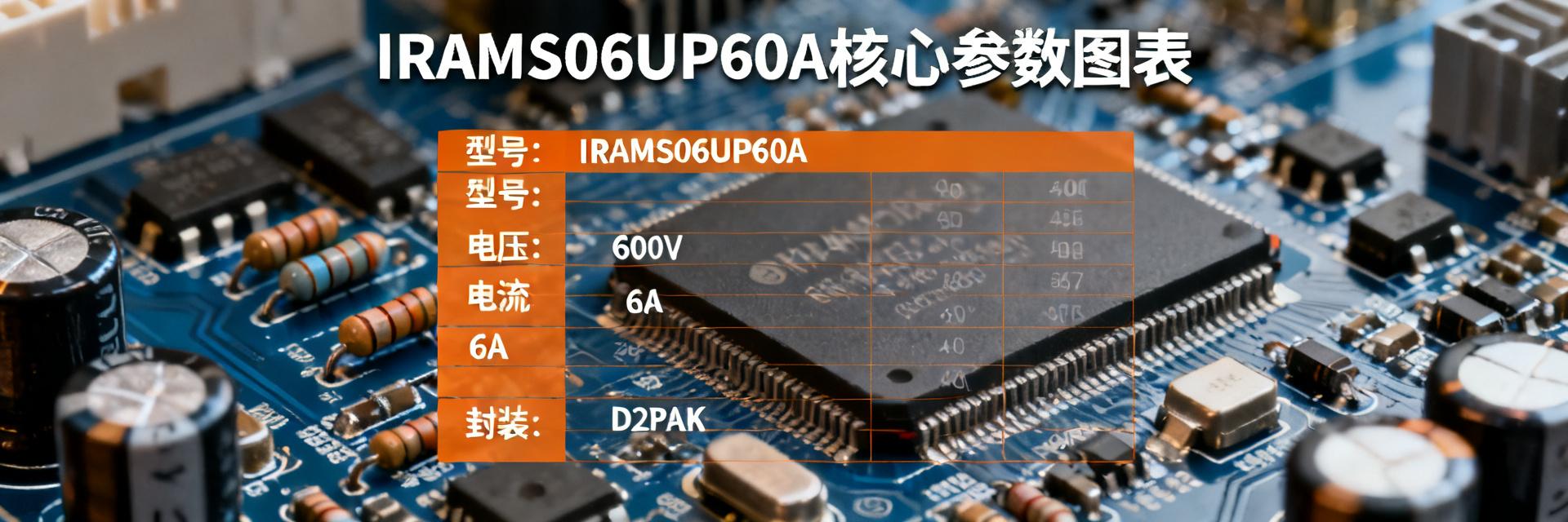
For example, the IRAMS06UP60A has a rated voltage of 600V. During design, you should ensure the maximum voltage in the circuit is far below this value. More importantly, all designs must operate within the "Recommended Operating Conditions" and include sufficient margin to ensure module stability and longevity.
Step 2: Dive into Electrical Characteristics and Functional Block Diagrams to Understand Internal Logic
Once you have mastered the basic specifications, the next challenge is to understand its internal "operational logic." The focus here is to combine the Electrical Characteristics table with the Functional Block Diagram to build a clear understanding of the module's internal working principles.
Analyzing Key Electrical Characteristic Parameters
The electrical characteristics table contains a wealth of data, but you don't need to memorize it all. For the IRAMS06UP60A, you should focus on the on-resistance RDS(on), switching times (such as td(on), tr, tf), and internal gate voltage. RDS(on) directly determines the conduction loss of the module, while switching times affect switching losses. For loss calculations, you should use typical values (Typ.) as a baseline for thermal design while referring to maximum values (Max.) to evaluate performance under worst-case scenarios.
Understanding the Relationship Between the Functional Block Diagram and Pin Definitions
The functional block diagram in the datasheet is the "map" for understanding the module's internal logic. You need to cross-reference it with the Pin Diagram. For instance, you will see pins like VCC, GND, VBS, HO, and LO. In the diagram, you'll notice integrated bootstrap diodes and bleeder resistors. This tells you that the external circuit requires a bootstrap capacitor, while functions like temperature monitoring are already integrated, helping you quickly determine which peripheral circuits are essential.
Key Summary
- ● Identity Positioning: The IRAMS06UP60A is an integrated power module for appliance motor drives; the front-page summary is a shortcut to quickly understanding its functions and application scenarios.
- ● Redline Parameters: Absolute maximum ratings (such as breakdown voltage and maximum current) are non-negotiable limits; designs must strictly follow recommended operating conditions with sufficient margin.
- ● Core Logic: Combining the electrical characteristics table and functional block diagram helps clarify internal logic and identify necessary peripheral circuits, thereby simplifying the design process.
